Drillings, DXF, MPR and CIX
EFS exports every board for CNC: the outline, cut-outs, holes and grooves. Any CAM program reads the DXF files, and on request EFS also writes WoodWOP MPR programs for Homag and CIX programs for Biesse. In this chapter you will see where the holes come from, how the board lies in the file, what each layer means and how to check the project before it goes to the machine.
Video: C04 Drillings, DXF, MPR and CIX
The same workflow in a one-and-a-half-minute video.
Before you start
- Open a project with cabinets. The holes come from the cabinet's hardware and joints on their own, so set those first in the Project hardware panel (see Project hardware) or in the Hardware and joints subpanel of each cabinet (see Hardware and joints).
- Bring back hidden fronts with the Show fronts button in the header. Fronts hidden with Shift+F do not go into the DXF either.
- Make an empty folder for the CNC files, e.g. DXF in the project folder. Why is explained in Folder and file names.
- Press Alt+Z for the see-through view: the dowels and holes show in the 3D view. Alt+Z again brings back the solid view.
The workflow from the video
The video uses a finished kitchen with project hardware: dowels, Blum Clip top hinges, TANDEMBOX drawers, adjustable shelves and bar handles.
- In the EFS tab open the Export panel, then the Settings subpanel at the bottom of the panel.
- Under CNC files, turn on CNC: WoodWOP MPR programs and CNC: Biesse CIX programs. See CNC file settings.
- Click a board of the sink cabinet.
- Click Export DXF - selected. In the file browser choose the folder and click Export DXF - selected at the bottom right. The program reports Export completed: 7 DXF. See Exporting DXF.
- Open the left door's DXF in the CAM program: the outline and the holes, each diameter and depth on its own layer. The hinge cups are on the layer
DRILL_D35_P13, the Ø8 hinge holes onDRILL_D8_P11.5and the Ø5 through holes for the handle onDRILL_D5_THRU. See Layers and colours. - Open the bottom's DXF: it has holes only in the edge, for the dowels from the side panels, on the layers
EDGE_LEFT_D8_P20andEDGE_RIGHT_D8_P20. See Face A and face B. - Look at the MPR and CIX programs of the same door. See MPR for Homag and CIX for Biesse.
- In the Export panel click Project check. See Project check.
Where the holes come from
You do not draw holes by hand. EFS drills them on its own, from the cabinet's hardware and joints, and rearranges them when you change the sizes. Every hole has a purpose, a diameter, a depth and the face of the board it goes into.
| Purpose | Which board | Holes (catalogue defaults) | Example layer in the DXF |
|---|---|---|---|
| Dowel (carcass joint Dowels) | The face of one board and the edge of the other: with an inset joint the side panels in the face, and the bottom, top, rails and fixed shelves in the edge | Ø8. A 30 mm dowel in an 18 mm board: 12 mm in the face, 20 mm in the edge. The first and last dowel 50 mm from the end of the joint. | DRILL_D8_P12, EDGE_LEFT_D8_P20 |
| Confirmat | A through hole in the board whose face meets the joint, a hole in the edge of the other board | Ø7 through; Ø5, depth 50 mm minus the board thickness plus 2 mm (34 mm with 18 mm) | DRILL_D7_THRU, EDGE_TOP_D5_P34 |
| Minifix | The bolt in the face of one board; in the other, a hole in the edge and the housing in the inner face, 24 mm from the joint | Bolt Ø5 × 11; edge Ø8 × 34; housing Ø15 × 12.5 | DRILL_D5_P11, EDGE_RIGHT_D8_P34, DRILL_D15_P12.5 |
| Hinge cup | Inner side of the door | Ø35 × 13, centre 21.5 mm from the edge (Hettich Sensys 22 mm). Hinges 96 mm from the top and bottom edge of the door, the others in between. | DRILL_D35_P13 |
| Hinge cup screw | Next to the cup (Blum Clip top, Hettich Sensys) | 2 × Ø8 × 11.5, 45 mm apart | DRILL_D8_P11.5 |
| Hinge mounting plate | Inner side of the side panel | 2 × Ø5 × 13, 37 mm from the side panel's front edge, 32 mm apart | DRILL_D5_P13 |
| Drawer slide | Inner side of the side panel | Ø4 × 12, the first hole 37 mm from the front edge, then every 128 mm | DRILL_D4_P12 |
| Handle | Doors, flaps and drawer fronts | Ø5 through; a bar handle two holes at Hole spacing, a knob one | DRILL_D5_THRU |
| Shelf support pin (adjustable shelves, System 32) | Inner sides of the side panels and both sides of dividers | Ø5 × 12, two rows: 37 mm from the front edge and 37 mm in front of the back, 32 mm grid | DRILL_D5_P12 |
| Worktop joint | Underside of both worktops in a corner joint | Ø35 × 20, 65 mm from the joint; two per joint, three when the joint is longer than 650 mm | DRILL_D35_P20 |
Where each is chosen:
| Holes | Field | Details |
|---|---|---|
| Dowels, confirmat, minifix | Joints type | Joints: dowels, confirmat, minifix |
| Hinges | Hinge type | Project hardware |
| Slides | Slide type | Project hardware |
| Handles | Handle | Handles |
| Shelf support pins | Shelf supports | Adjustable shelves, System 32 |
| Worktop joint | The 45° and Butt buttons in the worktop's EFS - Board tab | The worktop: cut-outs and the corner joint |
Rules the program applies on its own:
- A hinge or slide from the catalogue drills. No drilling (count only) only counts the hardware for the list, without a single hole.
- Fixed shelves (Fixed (dowels with the joints)) get dowels like the other joints. Adjustable shelves have no dowels; they rest on pins.
- When a hinge mounting plate lands on a shelf, EFS moves the whole hinge 32 mm up or down. A shelf pin hole that would land on a mounting plate or a slide is left out.
- A divider is drilled from both sides, so its shelf pin holes are shallow: at most half the divider thickness minus 0.5 mm.
- With Minifix and dowels, each minifix gets one dowel, 32 mm towards the middle of the joint.
- Flap mechanisms, wall unit hangers, legs and push latches do not drill holes. They only go into the hardware list.
Tip
The holes show in the 3D view in the see-through view (Alt+Z). Before exporting, look at one cabinet from all sides: you will see whether the hinge is on the right side and whether the shelf rows are where they should be.
Grooves, rebates and cut-outs
Besides holes, EFS also exports all other machining of the board:
| Machining | Where it comes from | How it is in the DXF |
|---|---|---|
| Groove for the back | Back → Construction: Grooved | Pocket: a closed polyline of the groove bottom on the layer POCKET_P10 (groove depth) |
| Rebate for the back | Back → Construction: Rebated | Pocket along the back edge, layer POCKET_P10 |
| Gola groove | The Gola profile subpanel | Part of the side panel's outline (layer CONTOUR) |
| L shape of a corner board | Corner cabinet | Outline with six points (CONTOUR) |
| Cut-out for a sink or hob | Cut-out on the worktop | A separate closed polyline on the layer CUTOUT |
| Mitred or butt cut of a corner joint | The 45° and Butt buttons on the worktop | Part of the worktop's outline |
| Cutter subpanel cut-out | The EFS - Board tab | Part of the outline |
| Siphon cut-out and pipe openings | Bathroom: siphon and pipes | Outline or CUTOUT; a board cut right through has several outlines |
Rules:
- A pocket is a recess that does not go through the board. The pocket depth is in the layer name.
- A rebate made of two strips in the model is joined by EFS into one rectangular pocket.
- A cut-out that goes through the whole board is
CUTOUT. A cut-out that touches the edge of the board changes the outline (CONTOUR).
Exporting DXF
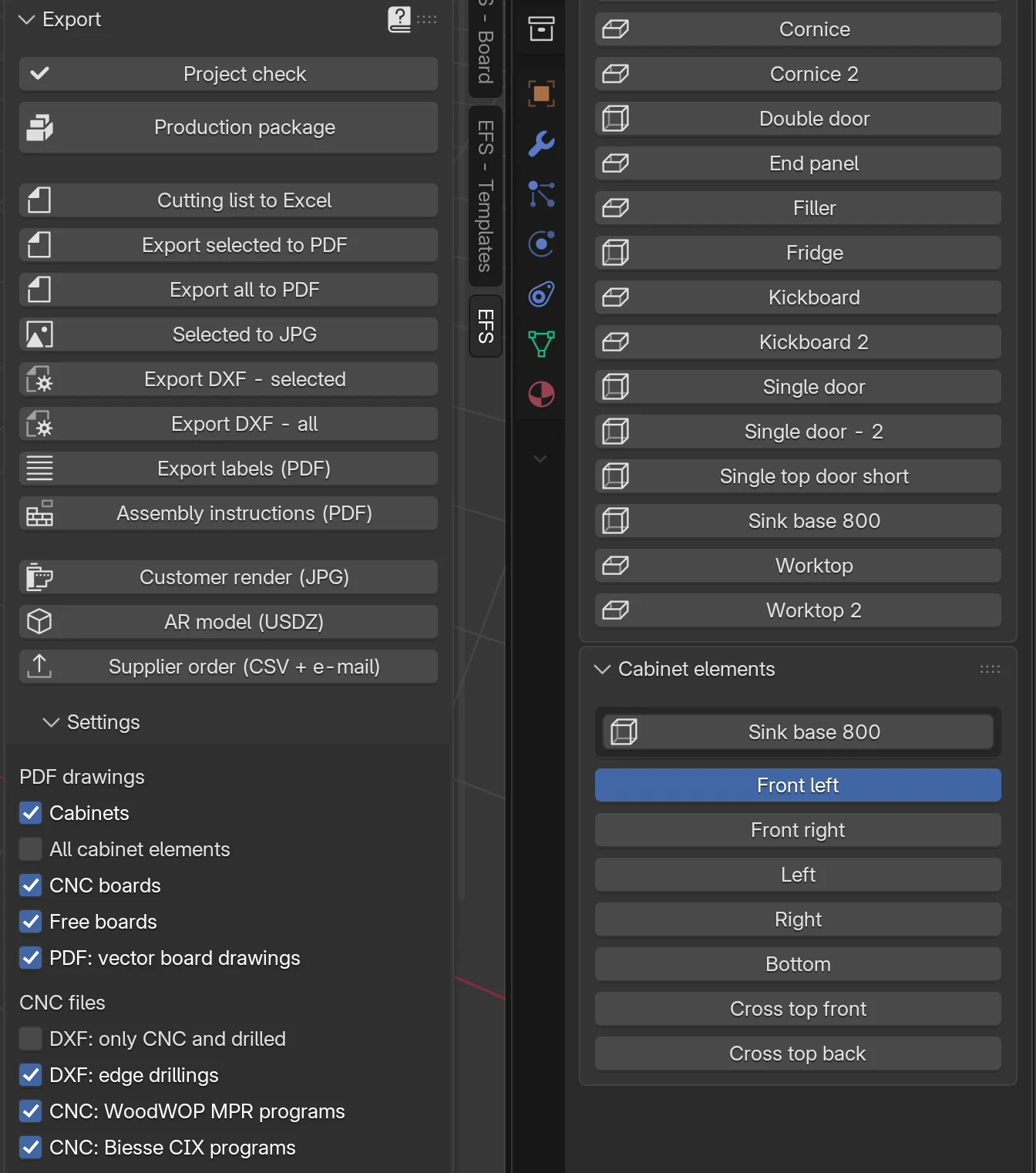
| Button | What it exports | When it is greyed out |
|---|---|---|
| Export DXF - selected | The boards of the selected cabinets and the selected free boards | Nothing is selected |
| Export DXF - all | All boards of the project | Never |
Export DXF - selected
- Click any board of a cabinet. For more cabinets, hold Shift and click boards of the others.
- In the Export panel click Export DXF - selected.
- In the file browser choose an empty folder. You make a new folder with the folder icon with a plus, left of the path.
- Click Export DXF - selected at the bottom right.
The program reports Export completed: 7 DXF: the number of DXF files written, B files included.
Rules:
- Selecting any board exports the whole cabinet it belongs to. The sink cabinet from the video gave 7 DXFs: two doors, two side panels, the bottom and two cross rails.
- A selected free board (worktop, kickboard, filler) exports only itself.
- The file name field at the bottom of the file browser is not used. EFS gives the names.
Export DXF - all
- In the Export panel click Export DXF - all.
- Choose an empty folder and click Export DXF - all.
All boards of the project are exported, free boards too. The selection has no effect. After the export EFS runs the Project check on its own. If it finds errors, it reports Exported, but the project check found 2 errors (Project check). The files are written anyway. Export DXF - selected does not run this check.
Folder and file names
All files go straight into the folder you choose, without subfolders:
| File | When | Example |
|---|---|---|
Cabinet_Board_LengthxWidthxThickness.dxf |
For each board of a cabinet, face A | Sudoperski_800_Vrata_lijeva_712x392x18.dxf |
Board_LengthxWidthxThickness.dxf |
For a free board | Radna_ploca_3228x596x38.dxf |
same name + _B.dxf |
The board has holes or a pocket on the other face too | ..._B.dxf |
same name + .mpr |
CNC: WoodWOP MPR programs is on and the board has holes or pockets | Sudoperski_800_Vrata_lijeva_712x392x18.mpr |
same name + .cix |
CNC: Biesse CIX programs is on and the board has holes | Sudoperski_800_Vrata_lijeva_712x392x18.cix |
index.csv |
Always | a list of all files of this export |
Rules for the names:
- The sizes in the name are the cut size (see Cut size in CNC files), e.g.
Donja_strana_763.2x561.2x18. - Croatian letters become plain ones (č → c, đ → d), spaces become
_, and other characters the file system dislikes also become_. - Two boards with the same name and size get the suffix
_2,_3…, e.g. two identical shelves.
Watch out
The export does not delete old files from the folder. The file name contains the size, so after you change a cabinet the old DXFs, with a different size, stay in the same folder. Use an empty folder for every export, or first delete the old .dxf, .mpr and .cix files. The Production package does this on its own: it puts the DXF files in the DXF subfolder and deletes the old ones before the export (see The production package and the supplier order).
index.csv
index.csv is a list of all files of the last export, one row per DXF file. The columns are separated by semicolons, and the file opens in Excel.
| Column | What it holds |
|---|---|
| File | Name of the DXF file |
| Cabinet | Name of the cabinet (for a free board, its own name) |
| Board | Name of the board |
| Material | Decor |
| Thickness | Thickness in mm |
| Length, Width | Cut size |
| Grain direction | Longer (grain along the longer side) or Shorter (along the shorter side). With the Croatian UI Dulja strana or Kraća strana |
| Face | A or B |
| Drillings | Number of holes in that file |
| CNC | CNC mark from the cutting list (CNC 1…), if the board has one |
What is in a DXF file
Each DXF file is one board, in DXF R12 (ASCII) format, in millimetres. Inside are the outline, cut-outs, holes, pockets and one line of text.
Origin and orientation
- The board is drawn as you see it when you look at its face A (see Face A and face B).
- The origin (0, 0) is the bottom left corner of the board.
- The X axis runs along the Length from the cutting list, that is, along the grain. The Y axis runs along the Width.
- The board has the cut size: the outline runs from (0, 0) to (Length, Width).
Example from the video: the left door is 716 mm high and the grain runs along the longer side. In the DXF the door lies down: X = 712 mm is the door height, Y = 392 mm the width. The cups are along the edge Y = 0, and the handle holes along the opposite edge.
Note
How the board lies in the file depends on the grain and face A, not on how it stands in the cabinet. Go by the origin and the dimensions in the file, not by the 3D view.
Layers and colours
| Layer | Colour (ACI) | What it is | Example |
|---|---|---|---|
CONTOUR |
7, white (black on a light background) | Board outline, a closed polyline. A board cut right through has several outlines. | |
CUTOUT |
2, yellow | A cut-out through the board inside the outline, a closed polyline | sink cut-out |
DRILL_DØ_Pdepth |
1, red | A hole in the face of the board: a circle of diameter Ø, depth in the name | DRILL_D35_P13 |
DRILL_DØ_THRU |
1, red | Through hole | DRILL_D5_THRU |
EDGE_side_DØ_Pdepth |
4, cyan | Hole in the edge. Side: LEFT (X = 0), RIGHT (X = Length), BOTTOM (Y = 0), TOP (Y = Width) |
EDGE_LEFT_D8_P20 |
POCKET_Pdepth |
6, magenta | Pocket (bottom of a groove or rebate), a closed polyline | POCKET_P10 |
INFO |
8, grey | Text below the board |
Rules:
- Diameter and depth are in millimetres, to one decimal place and without trailing zeros:
P11.5,P20,P12.5. - A hole is a through hole when its depth reaches the board thickness (to within 0.05 mm). Through holes are always in the face A file.
- An edge hole is drawn as a circle right on the edge of the board, at the hole's position along the edge. The DXF does not carry the hole's height within the thickness; EFS drills edge holes in the middle of the board thickness.
- Edge holes are only in the face A file, and only with DXF: edge drillings turned on.
- The text on the
INFOlayer sits 14 mm below the board: Cabinet / Board / Length x Width x Thickness mm / Material, and in the B file B at the end. Example:Sudoperski 800 / Vrata lijeva / 712x392x18 mm / U702 ST9 Kasmir siva. The text has no Croatian letters.
Tip
Before the first batch, load the DXF of one board into your CAM program and assign an operation to each layer: to the layer DRILL_D8_P12 an Ø8 drill 12 mm deep, and so on. Diameter and depth are in the layer name, so rules you set up once apply to all boards.
Face A and face B
Face A is the side of the board that most holes go into. EFS chooses it on its own:
| Board | Face A |
|---|---|
| Door | Inner side, with the cups |
| Side panel | Inner side, with the dowels, hinge mounting plates, slides and shelf pins |
| Bottom with minifix fittings | Inner side, with the housings |
| Worktop with connectors | Underside: the worktop is drawn as seen from below |
| Board with edge holes only, or with no holes | One side, by the program's rule |
When the board has holes or a pocket on the other side too, EFS writes one more file, with the suffix _B:
- The B file shows the same board as seen from face B. It is mirrored left to right: a hole at X becomes a hole at Length − X, and Y stays the same.
- The origin is again the bottom left corner, as the machine drilling face B sees it.
- The B file holds only the holes and pockets of face B. The outline is the same, mirrored.
- MPR and CIX then also have their own
_Bprogram.
A B file is made, for example, for a divider with shelves on both sides: dowels or shelf pins go into both of its faces.
Cut size in CNC files
The CNC cuts and drills before edge banding. That is why DXF, MPR and CIX have the board at the cut size, and every hole is measured from the cut edges:
- The outline runs from 0 to the cut size (see Finished size and cut size).
- Holes move by the edge tape thickness on the left and bottom edge.
- Points on the right and top edge follow the new edge.
- Cut-outs and pockets that are not on the edge keep their shape.
The PDF drawing of the board stays at the finished size, with holes measured from the finished edges.
Example, a 716 × 396 mm door with 2 mm edge tape all round and a Blum Clip top hinge:
| PDF drawing | DXF, MPR, CIX | |
|---|---|---|
| Board | 716 × 396 mm | 712 × 392 mm |
| Cup from the long edge of the door (cup distance) | 21.5 mm | 19.5 mm |
| First cup from the short edge of the door | 96 mm | 94 mm |
Watch out
When you compare the DXF with the PDF, the sizes differ by the edge tape thickness. That is correct. Do not "fix" the positions in CAM to match the PDF.
MPR for Homag (WoodWOP)
With CNC: WoodWOP MPR programs turned on, EFS writes an .mpr program of the same name next to every DXF. The program has only drillings and pockets. The MPR has no board outline: the board comes from the saw, and a shape that is not a rectangle is cut from the DXF.
| Block | What it is | Fields |
|---|---|---|
[H |
Header | VERSION="4.0" |
<100 \WerkStck\ |
Workpiece | LA length, BR width, DI thickness (cut size) |
<101 \Kommentar\ |
Comment | KM: Cabinet / Board, with / B for face B and / contour in DXF when the board is not a rectangle |
<102 \BohrVert\ |
Drilling into the face | XA, YA position; DU diameter; TI depth; DT 1 through, 0 blind |
<103 \BohrHoriz\ |
Drilling into the edge | XA, YA position on the edge; ZA half the thickness; BM side: XM left edge, XP right, YM bottom, YP top; DU, TI |
<105 \Tasche\ |
Pocket (groove, rebate) | XA, YA corner; LA, BR size; TI depth |
Rules:
- An MPR is made only for a board that has holes or pockets. A board without machining has no program.
- Origin and orientation are the same as in the DXF. The
_Bprogram drills face B. - Edge holes (
BohrHoriz) go into the program only with DXF: edge drillings turned on. - Only rectangular pockets are included.
CIX for Biesse
With CNC: Biesse CIX programs turned on, EFS writes a .cix program next to every DXF. The CIX has only drillings. Outline, grooves and rebates stay in the DXF.
| Block | What it is | Fields |
|---|---|---|
BEGIN ID CID3 |
Header | REL= 5.0 |
BEGIN MAINDATA |
Workpiece | LPX length, LPY width, LPZ thickness (cut size); CUSTSTR: Cabinet / Board |
BEGIN MACRO, NAME=BG |
One drilling | SIDE side; CRN "1" (corner X0/Y0); X, Y, Z position; DP depth; DIA diameter; THR YES for a through hole |
Sides (SIDE):
| SIDE | Side of the board | Same as in the DXF |
|---|---|---|
| 0 | Face (top surface) | DRILL_… |
| 1 | Bottom edge (Y = 0) | EDGE_BOTTOM_… |
| 2 | Right edge (X = LPX) | EDGE_RIGHT_… |
| 3 | Top edge (Y = LPY) | EDGE_TOP_… |
| 4 | Left edge (X = 0) | EDGE_LEFT_… |
Rules:
- A CIX is made only for a board with holes. A board with only a groove has no CIX.
- Edge holes have
Zin the middle of the board thickness. - The
_Bprogram drills face B, as the B file does.
Watch out
MPR and CIX are a preview version. The UI says: validate on the machine before production. Run the first program on a test board and compare it with the PDF drawing (allowing for the edge tape difference).
In MPR and CIX programs Croatian letters are written without diacritics: č and ć as c, š as s, ž as z, and đ as dj, e.g. Gornja poprecna ploca.
CNC file settings
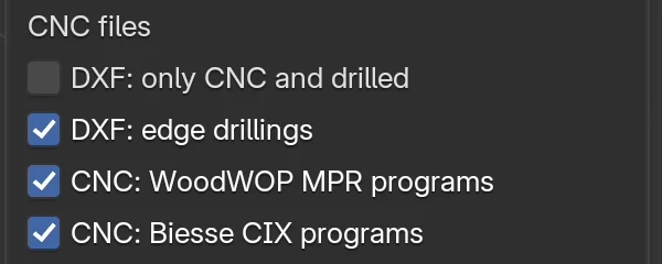
The CNC checkboxes are in the Export panel, Settings subpanel, under CNC files. They apply to both DXF buttons and to the Production package. All checkboxes of the subpanel are described in Export settings.
| Option | What it does | Default | Values |
|---|---|---|---|
| DXF: only CNC and drilled | The export skips plain rectangles without holes and pockets. They are cut from the cutting list. | off | on, off |
| DXF: edge drillings | Edge holes (layers EDGE_…) go into the DXF, and horizontal drillings into MPR and CIX. |
on | on, off |
| CNC: WoodWOP MPR programs | Next to the DXF, writes an .mpr program per board (drillings and pockets) for Homag/WoodWOP. |
off | on, off |
| CNC: Biesse CIX programs | Next to the DXF, writes a .cix program per board (drillings) for Biesse. |
off | on, off |
| PDF: vector board drawings (under PDF drawings) | The board pages in the PDF are technical drawings with holes and dimensions. See Vector PDF board drawings. | on | on, off |
Only boards with machining
With DXF: only CNC and drilled, the export writes only boards that have at least one of these:
- a CNC mark from the cutting list (corner boards, worktops with a cut-out or a corner joint, a Cutter subpanel cut-out);
- at least one hole, in the face or in the edge;
- a pocket (groove or rebate for the back).
Left out are, for example, backs, shelves on pins, fronts without handles and hinges, and drawer parts without holes. The cutting list still has them, so the saw cuts them from it.
Note
A board that has only edge holes (e.g. a bottom with dowels) goes into the export even when DXF: edge drillings is off. Its DXF then holds only the outline.
Vector PDF board drawings
With PDF: vector board drawings turned on, every board page in the PDF (Export all to PDF, Export selected to PDF) has a technical drawing. The drawing is not rendered, so the PDF is ready quickly and stays sharp at any zoom. How the PDF is exported is described in PDF drawings.
The board is drawn as in the DXF (face A, origin at the bottom left, Length horizontal), but at the finished size.
| On the drawing | What it means |
|---|---|
| Black line, light grey area | Board outline. A cut-out is white. |
| Blue dashed line with a number, e.g. -10 | Pocket (groove or rebate) and its depth; (B) means it is on face B |
| Thick blue line along an edge, with a number | Edge tape on that edge and its thickness. Edge 1 is the bottom or left one, edge 2 the top or right one. |
| Grey double arrow in the middle | Grain direction (always horizontal, along the Length) |
| Circle, solid line | Hole in face A |
| Circle, dashed line | Hole in face B |
| Number next to or inside the hole | Hole depth in mm; thru for a through hole |
| Dashed rectangle from the edge inwards | Edge hole, as long as the hole is deep, with the depth at its end |
| Numbers below and left of the board | Hole positions from the bottom left corner: X below, Y on the left, in whole mm |
| Dimensions with arrows, furthest from the board | Length below and Width on the left |
Hole colours by purpose (the same in the legend below the drawing):
| Colour | Purpose |
|---|---|
| blue | Dowel |
| red | Hinge cup, Hinge cup screw, Hinge mounting plate |
| green | Drawer slide |
| orange | Shelf support pin |
| turquoise | Confirmat |
| brown | Minifix |
| purple | Handle |
| black | Worktop joint |
Below the drawing is the Drilling legend table: one row for each group of holes with the same purpose, face, diameter and depth.
| Column | What it holds |
|---|---|
| (colour) | Colour of the holes on the drawing |
| Drilling legend | Purpose: Dowel, Hinge cup… |
| Ø × depth | e.g. Ø35 × 13 mm or Ø5 thru |
| Face | face A, face B, left edge, right edge, bottom edge or top edge |
| Qty | Number of holes in the group |
| Positions X/Y | Position of each hole from the bottom left corner, e.g. (96, 22); (620, 22) |
Without the PDF: vector board drawings checkbox, the board page is a rendered image of the board with dimensions and dowel hole marks. The export then takes longer, and the hardware holes are not dimensioned.
Checks before CNC
Project check
Project check looks for errors in the project before export. It is the first button in the Export panel.
- In the EFS tab open the Export panel.
- Click Project check.
- If there are no problems, the program reports No problems found.
- Otherwise a window with a list opens. Next to a finding about a board or a cabinet there is an arrow button (Show in the scene): it selects that object and zooms the view to it.
- Fix the problem and click Project check again.
- OK closes the window and reports 3 problems found. Esc or Cancel closes it without a message.

The window shows at most 40 findings, and below it says how many more there are. Errors have a warning icon, and the other findings an i icon.
Cutting list to Excel and Export DXF - all run the check on their own, after the export. They report only errors: Exported, but the project check found 2 errors (Project check).
Hole messages
| Message | Type | Meaning | What to do |
|---|---|---|---|
| Dowel hole Ø8 in 'Left' (Cabinet 1) goes through the board. | error | A dowel hole in the face goes through the whole board: less than 0.5 mm is left. | Reduce Face hole depth or Dowel length in the Hardware and joints subpanel, or use a thicker board. |
| Hole Ø8×15 in 'Left' (Cabinet 1) leaves only 3.0 mm of material. | warning | Less than 4 mm is left below a dowel hole, and less than 2.5 mm below other holes. | Same as above. For a hinge cup, check the front thickness. |
| 3 cabinets have doors without hinge drillings (Project hardware). | warning | Cabinets with doors have the hinge No drilling (count only). | In Project hardware, choose a hinge from the catalogue and apply it. |
| 2 cabinets have drawers without slide drillings (Project hardware). | warning | The same for slides. | Choose a slide from the catalogue. |
| 4 cabinets have no dowel joints (Project hardware). | warning | Cabinets have Joints type: None: the side panels have no joint holes at all. | Choose Dowels, Confirmat or Minifix. |
| Door 'Front left' (Cabinet 2) has no hinges. | warning | The number of hinges is 0. | Enter Hinges or turn on Auto hinge count. |
| Shelf 'Shelf horizontal' (Wardrobe) does not rest on its pins: reduce its front or back recess. | warning | An adjustable shelf does not reach the front or back row of pins. | Reduce the shelf's Front recess or Back recess. See Adjustable shelves, System 32. |
The check does not report edge holes or through holes for handles and the confirmat head: those are intentional.
Example of a warning: with Face hole depth 15 mm, a dowel in an 18 mm board leaves 3 mm, so the check reports a warning. With the default automatic depth (board thickness minus 6 mm) this does not happen.
Other messages
The check also reports overlapping cabinets (error), doors that hit a neighbour or a wall when opened, decors without a price, duplicate cabinet names and sliding doors made for a different width. All messages are described in the chapter The production package and the supplier order.
Note
The check does not know about fronts hidden with Shift+F: they are not in the export, so it does not check them either. Before the check, bring the fronts back with the Show fronts button.
Checklist before the machine
- The fronts are visible (the Show fronts button in the header is blue).
- Hinge type, Slide type and Joints type are from the catalogue, not No drilling (count only) and None.
- Project check has no errors.
- The holes have been checked in the see-through view (Alt+Z) on at least one cabinet of each kind.
- The export goes into an empty folder.
- In CAM the layers are assigned to operations, and the first board has been checked against the PDF drawing, allowing for the edge tape difference.
- The MPR or CIX has been run for the first time on a test board.
- Boards with a
_Bfile are marked for a second pass: the machine drills face B after the board is turned over.
Common problems and solutions
Export DXF - selected is greyed out. Nothing is selected. Click a board of a cabinet or a free board.
There are more DXFs in the folder than boards. The folder was not empty. Old DXFs with a different size in the name were left from the previous export. Delete them or export to a new folder. What is in the last export is listed in index.csv.
The holes in the DXF are 2 mm off compared with the PDF. The DXF is at the cut size, and the PDF at the finished size. The difference is the edge tape thickness. See Cut size in CNC files.
A board has no DXF. DXF: only CNC and drilled is on, and the board is a plain rectangle without holes. Or it is a front hidden with Shift+F, or a board set to None.
The DXF has no edge holes. DXF: edge drillings is off. Turn it on and export again.
The door has no hinge holes. Hinge type is No drilling (count only). Choose a hinge from the catalogue in the Hardware and joints subpanel or in Project hardware.
A board has no MPR or CIX program. The board has no holes (and, for MPR, no pockets). A program is made only for a board with machining. CIX has no pockets, so a board with only a groove has no CIX.
A board has two files, with and without _B. The board has holes or a groove on both sides. The _B file is the other face, mirrored.
The board is turned differently in CAM than in the cabinet. The DXF draws the board as seen from face A, with the Length along the X axis. See Origin and orientation.
The sink cut-out is mirrored in the worktop's DXF. A worktop with connectors is drawn as seen from below, because the connector holes are on the underside.
The file name has no Croatian letters. DXF and file names use plain letters only (č → c). The real name is in index.csv.
The check reports that a dowel hole goes through the board. Face hole depth is too large for that board, or the board is thinner than the others. See Hole messages.
Clicking an export reports an error about the trial or the subscription. Exports are stopped. See When the free trial or the subscription ends.
Shortcuts in this chapter
| Key | Action |
|---|---|
| Alt+Z | See-through view: dowels and holes show |
| Shift+F | Hide fronts: hidden fronts do not go into the DXF |
| Shift + click | Add a cabinet to the selection for Export DXF - selected |
| Esc | Close the Project check window |
| Ctrl+Shift+E | Production package: DXF into the DXF subfolder, with the cutting list, drawings and the rest |
All shortcuts are in the chapter Keyboard shortcuts.
Next
Next chapter: Nesting and board prices