Adjustable shelves, System 32
Adjustable shelves stand on support pins in rows of Ø5 holes 32 mm apart. In this chapter you choose the shelf supports, see where EFS drills the rows of holes and how the shelves snap to the grid. At the end come the compartments between dividers, and the support pins in the hardware list and the price.
Video: C03 Adjustable shelves, System 32
The same workflow in a video of a minute and a half.

Before you start
- Open a project with a cabinet that has at least one horizontal shelf. How shelves are added and what the fields of the Shelves box mean is explained in the chapter How a cabinet is built.
- The Shelf supports field shows only when the cabinet has a horizontal shelf. A corner cabinet has no adjustable shelves.
- You see the inside when you open the doors with O or hide the fronts with Shift+F. You see the holes in the X-ray view, key Alt+Z.
Watch out
Fronts hidden with Shift+F don't go into the cutting list, PDF, DXF, labels, quote or render. Before exporting, bring them back with the fronts icon in the header of the 3D Viewport.
The workflow from the video
In the video there is a finished kitchen whose Project hardware is set to adjustable shelves with holes around the shelves. The wall unit Double door (800 × 350 × 720 mm) has two shelves.
- Click a board of the cabinet and open the EFS - Cabinet tab.
- Open the Shelves box. Under Shelf supports it says Adjustable, System 32 around the shelves. See Shelf supports.
- Press Alt+Z for the X-ray view. In both side panels you see two rows of holes, front and back, around each shelf. See Rows of holes.
- In the Shelf supports field, choose Adjustable, System 32 full rows. The holes now run the full height of the side panel.
- Press Shift+H for a new horizontal shelf. The lowest shelf stays where it is, and the others snap to the 32 mm grid. See Shelves on the grid.
- Press Shift+V for a vertical shelf (divider). The cabinet gets two compartments.
- In the New shelves in compartment field, type 2 and press Enter. Press Shift+H: the new shelf goes into the right compartment. The divider gets holes too. See Compartments and dividers.
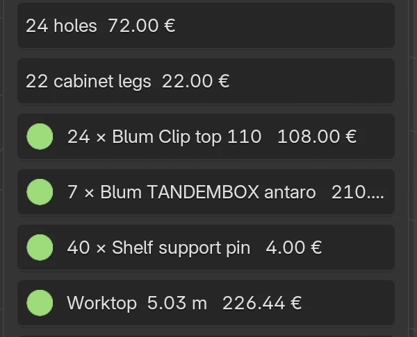
- In the EFS tab, open Cost estimate. The list has a Shelf support pin row. See Support pins in the hardware list and the price.
Shelf supports
The Shelf supports field in the Shelves box decides how the shelves are held. The same field is in Project hardware.
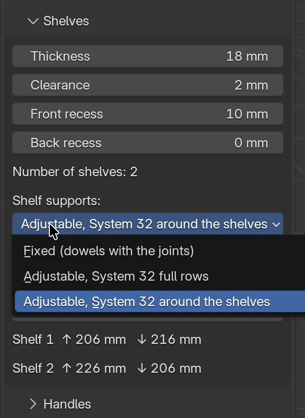
| Option | What you get | Holes for support pins | Joint between shelf and side panel |
|---|---|---|---|
| Fixed (dowels with the joints) | The shelves stand exactly where you put them, evenly spaced and with the offset you type. Default. | None | The same joint as the carcass: dowels, confirmat or minifix from the Joints type field. With Joints type: None the shelf has no joint. |
| Adjustable, System 32 full rows | The shelves rest on support pins. The holes run the full height of the side panel, so the customer can move a shelf anywhere. | Two rows, the full height | No dowels or other joints in the shelves |
| Adjustable, System 32 around the shelves | The shelves rest on support pins. There are holes only around each shelf, so the side panel looks cleaner. | Two rows, seven holes around each shelf | No dowels or other joints in the shelves |
When you change the option, EFS rearranges the shelves at once, drills the holes and changes the dowels. When you go back to Fixed (dowels with the joints), the holes disappear and the shelves get joints again.
Where you choose it
| Place | What it affects |
|---|---|
| EFS - Cabinet tab, Shelves box, Shelf supports field | Only this cabinet. The field shows only when the cabinet has a horizontal shelf. |
| EFS tab, Project hardware panel, Shelves box, Shelf supports field | New cabinets and templates. You change existing cabinets with the Apply to all or Apply to selected button: the shelves snap to the grid and get holes, as when you change the field in the cabinet. See Project hardware. |
Project hardware is also saved in My settings, so a new project can start with adjustable shelves straight away. See Working faster.
Note
The templates Wardrobe, 2 doors, hanging rail, Wardrobe with drawers, Wardrobe, 3 doors and Hall wardrobe always come with fixed shelves. Shelf supports from Project hardware don't change them. The other templates get Shelf supports from Project hardware. On those wardrobes, switch on adjustable shelves in the Shelves box or with the Apply to selected button.
System 32 sizes
| Size | Value |
|---|---|
| Hole diameter | 5 mm |
| Hole depth | 12 mm; in a divider at most half the divider thickness minus 0.5 mm (8.5 mm in an 18 mm divider) |
| Hole spacing in a row | 32 mm |
| Front row | 37 mm from the front edge of the side panel |
| Back row | 37 mm in front of the back |
| Edge clearance | Holes at least 40 mm above the bottom and 40 mm below the top board |
| Support pin hole | 4 mm below the underside of the shelf |
| Holes around a shelf (around the shelves) | The support pin hole and three holes above and three below it |
| Support pins per shelf | 4 |
For advanced users
The sizes are in the catalogue shelf_supports.json, as for hinges and slides. Put your own sizes in a file of the same name in the user_hardware folder in your user folder (see Where your data is). An entry with the key SYSTEM32 or SYSTEM32_ZONE replaces the supplied option, and an entry with a new key adds a new option to the menu. Every adjustable system must have the hole diameter and depth, the spacing, both rows, the edge clearance, the hole distance below the shelf and the number of support pins per shelf. EFS skips an entry without one of these sizes.
Rows of holes
EFS drills two rows of holes in the inner face of both side panels: a front row and a back row. The grid goes through the hole 4 mm below the lowest shelf, every 32 mm up and down.
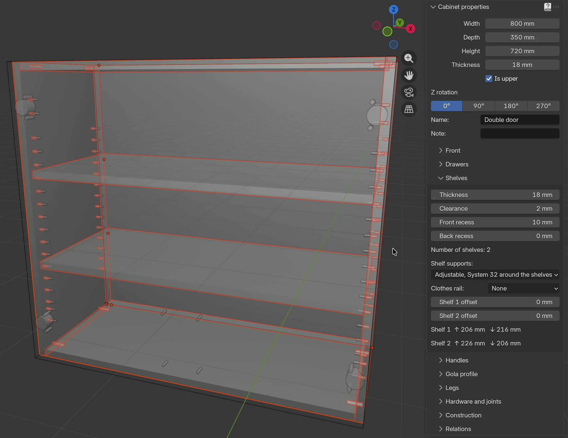
Where the rows go:
- Front and back. The front row is 37 mm from the front edge of the side panel. The back row is 37 mm in front of the back. When the back is in a groove or rebate, the back row moves forward with the back. A cabinet without a back has the back row 37 mm from the rear edge of the side panel.
- Bottom and top. The 40 mm edge clearance is measured from the top face of the bottom and from the underside of the top board. When the bottom is raised (Engagement of the bottom), the holes start above it. If the cabinet has no top board (e.g. it has cross boards), the clearance is measured from the top edge of the side panel.
- Mounting plate holes. The hinge mounting plate sits 37 mm from the front edge, in the same row. EFS leaves out a support pin hole that would fall too close to a mounting plate hole or a slide hole.
Full rows
With Adjustable, System 32 full rows the holes run from the first grid point at least 40 mm above the bottom to the last point at least 40 mm below the top board. The first hole is therefore between 40 and 72 mm above the bottom, depending on where the lowest shelf is.
Around the shelves
With Adjustable, System 32 around the shelves EFS drills only the support pin hole and three holes above and three below it. That is seven holes per shelf in each row. When shelves are closer than seven holes, the zones merge and no hole is repeated. The 40 mm edge clearance applies here too.
Example
A cabinet 720 mm high with 18 mm boards and two shelves (the cabinet from the video):
- The shelves sit at 234 and 458 mm above the bottom edge of the cabinet (underside of the shelf).
- The support pin holes are 4 mm lower, at 230 and 454 mm.
- Full rows: holes from 70 to 646 mm, 19 in each row, 38 in the side panel.
- Around the shelves: holes from 134 to 550 mm, 14 in each row, 28 in the side panel.
Shelves on the grid
Adjustable shelves rest on support pins, so each one must be on the grid. EFS does this itself:
- The shelves are spread at equal spacing, like fixed ones, with the offset from the Shelf offset field.
- The lowest shelf stays where it is.
- Every other shelf snaps to the nearest point of the 32 mm grid, counted from the lowest shelf. A shelf moves at most 16 mm up or down.
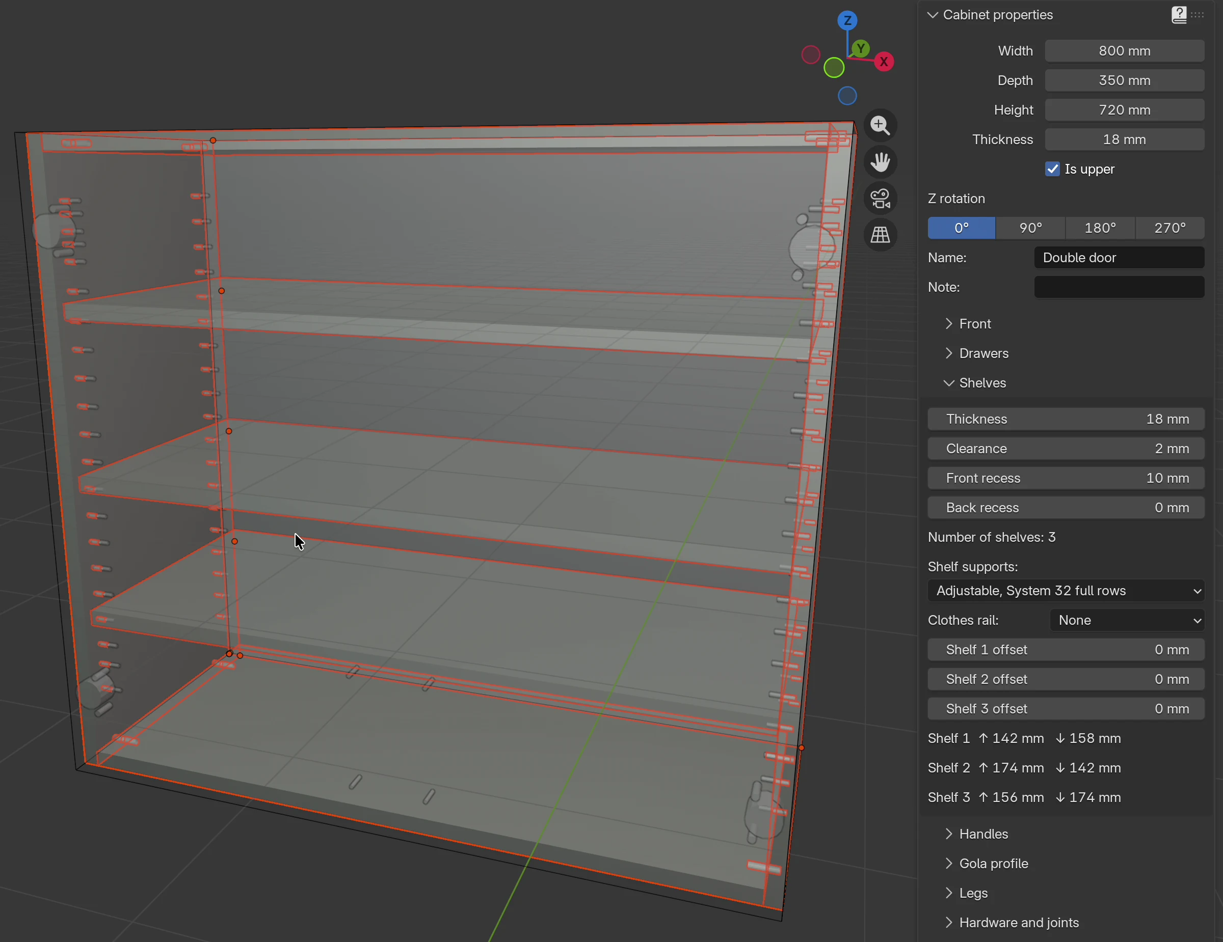
In the video: the cabinet has two shelves 234 mm apart. When you switch on System 32, the upper shelf snaps 10 mm lower, to 7 × 32 = 224 mm from the lower one. In the Shelves box the spacings change from Shelf 1 ↑ 216 mm ↓ 216 mm to Shelf 1 ↑ 206 mm ↓ 216 mm and Shelf 2 ↑ 226 mm ↓ 206 mm.
Every new shelf (Shift+H) rearranges all the shelves of the cabinet: they spread to equal spacing and then snap to the grid again.
Shelf offset
The fields Shelf 1 offset … Shelf 10 offset also work with adjustable shelves, but the result snaps to the grid:
- The lowest shelf's offset moves the whole grid and all the holes. The other shelves snap to the nearest point of the new grid.
- The other shelves' offset goes in steps of 32 mm. EFS rounds it to the nearest grid point, so an offset under 16 mm doesn't move the shelf.
- If you move a shelf below the one that was lowest so far, it becomes the lowest and the grid starts from it.
Tip
Follow the spacings in the Shelf 1 ↑ … mm ↓ … mm rows under the offset fields. These are the clear spaces above and below each shelf, after rounding to the grid.
A shelf that doesn't rest on its pins
The shelf must cover both rows of holes: the support pin must be at least 3 mm inside the shelf, at the front and at the back. When the shelf is recessed too far, Project check (EFS tab, Export panel) reports:
Shelf 'Shelf horizontal' (Cabinet name) does not rest on its pins: reduce its front or back recess.
The recess in the message means the Front recess and Back recess fields in the Shelves box. With the default rows at 37 mm, the shelf rests on the pins as long as both recesses are 34 mm at most.
- Click the icon at the end of the message row (Show in the scene): EFS selects that shelf and zooms the view in on it.
- In the Shelves box, reduce Front recess or Back recess to 34 mm or less.
- Run Project check again.
The check looks only at shelves that have holes 4 mm below them.
The holes are 12 mm deep, so the side panel must be at least 14.5 mm thick. For a 13 or 14 mm side panel Project check reports Hole Ø5×12 in '…' (…) leaves only … mm of material. Details about the check are in the chapter The production package and the supplier order.
Compartments and dividers
A vertical shelf (divider) splits the cabinet into compartments. Compartments are counted from the left: the left one is 1. Each horizontal shelf lies in one compartment and is spaced together with the shelves of that compartment.
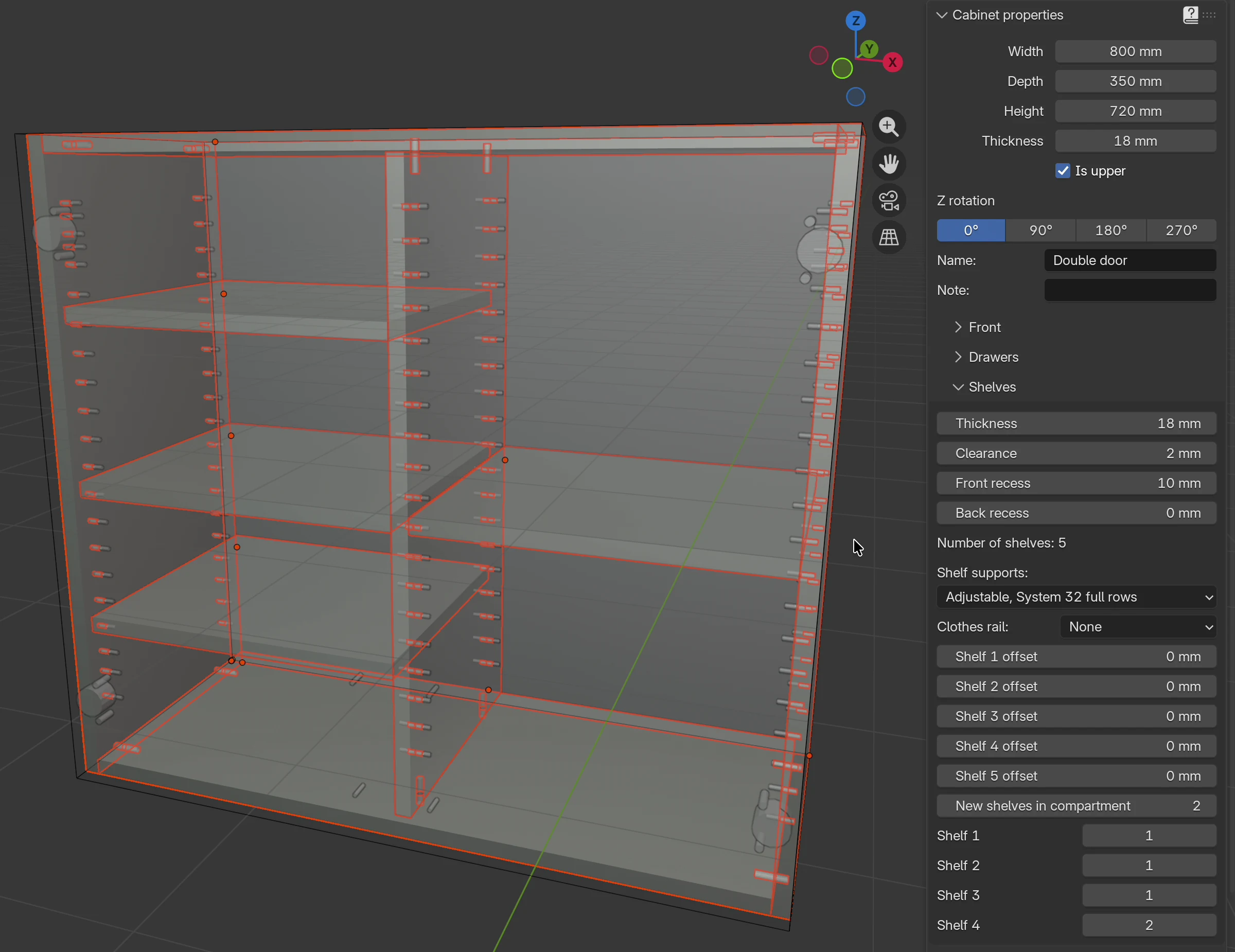
- Click a board of the cabinet (not a shelf).
- Press Shift+V or click Add → Vertical shelf.
- In the Shelves box, type the compartment number in New shelves in compartment and press Enter.
- Press Shift+H. The new shelf goes into that compartment.
- To move a shelf that is already in the cabinet, use its Shelf 1, Shelf 2… field: type the compartment number.
| Option | What it does | Default | Values |
|---|---|---|---|
| New shelves in compartment | Which compartment the next horizontal shelf goes into, counting from the left. Doesn't change existing shelves. | 1 | 1–11 |
| Shelf 1, Shelf 2… | The compartment that horizontal shelf lies in. Shelves are numbered in the order they were added, without the dividers. | the compartment the shelf was added to | 1–11 |
The fields show only when the cabinet has a divider. If you type a number larger than the number of compartments, the shelf goes into the rightmost compartment.
How System 32 works with compartments:
- Only the side panel and the divider that bound a compartment with shelves get holes. An empty compartment has no holes.
- A divider gets holes on both sides when there are shelves in both neighbouring compartments. The holes in a divider are shallower than half its thickness (8.5 mm in an 18 mm divider), so the two sides don't meet.
- The grid is the same for the whole cabinet: all shelves, in all compartments, snap to the grid of the cabinet's lowest shelf.
- Support pins are counted as without dividers: four for each horizontal shelf, in all compartments.
Note
Each shelf remembers the number from the New shelves in compartment field at the moment it was added, and the default is 1. So shelves added before the first divider stand in the left compartment after it. Arrange them with the Shelf 1, Shelf 2… fields.
Watch out
The numbers in the Shelf offset fields and in Shelf 1, Shelf 2… are not the same. Shelf offset also counts the dividers, in the order they were added, while Shelf N counts only horizontal shelves. In the video the divider was added fourth, so Shelf 4 (the first shelf in the right compartment) is in the Shelf 5 offset field.
Compartments in a wardrobe, a hanging rail in a compartment and hat shelves are described in the chapter A wardrobe with compartments and a rail.
Support pins in the hardware list and the price
EFS counts four support pins for each horizontal shelf of a cabinet with adjustable shelves. Fixed shelves have no support pins.
| Where | What it says |
|---|---|
| The cutting list in Excel, Hardware sheet, and the hardware page in the PDF | A row per cabinet: Shelf support pin, Ø5, quantity. At the bottom the total for the whole project. See Cutting list and cut size. |
Hardware order (order_hardware.csv) |
The total of support pins for the project. See The production package and the supplier order. |
| Cost estimate (EFS tab) | A N × Shelf support pin row with the price. |
| Quote | Support pins among the hardware. See A quote for the customer. |
The price of a support pin is in the price list, Other sheet, row SHELF_PIN_5. In the default price list a support pin costs 0.10 EUR. How to change the price list is explained in the chapter Nesting and board prices.
In the video the whole kitchen has ten shelves on support pins, so the Cost estimate says 40 × Shelf support pin, 4.00 EUR in total.
Holes in DXF and on the CNC
Support pin holes are ordinary drillings in the face of the side panel and the divider. They go into DXF, MPR, CIX and the PDF drawings like the other drillings.
- In DXF they are on the layer
DRILL_D5_P12, and in an 18 mm divider on the layerDRILL_D5_P8.5. - On the PDF drawing of a board the holes are orange, and the legend says Shelf support pin.
Layers, board sides and CNC formats are described in the chapter Drillings, DXF, MPR and CIX.
Common problems and solutions
I can't see the Shelf supports field. The cabinet has no horizontal shelf. Add one with Shift+H. A corner cabinet has no adjustable shelves.
The shelf moved when I switched on System 32. Shelves snap to the 32 mm grid, counted from the lowest shelf. The move is at most 16 mm. If you need a different grid, move the lowest shelf with the Shelf offset field.
I typed a shelf offset, and the shelf didn't move. With adjustable shelves the offset goes in steps of 32 mm. EFS rounds an offset under 16 mm back to the same grid point. Type 32, 64… mm.
Project check reports that a shelf doesn't rest on its pins. The shelf is recessed more than 34 mm at the front or back. Reduce Front recess or Back recess.
There are no holes in the divider. The compartment on that side of the divider has no shelves. Holes appear only next to compartments with shelves.
The shelf went into the wrong compartment. New shelves in compartment affects only the next new shelf. Move an existing one with the Shelf N field.
There are no shelf support pins in the hardware list. The cabinet has Fixed (dowels with the joints), or the wardrobe template came with fixed shelves. Choose an adjustable option in the Shelves box.
The shelves still have dowels. The cabinet has fixed shelves. With adjustable shelves EFS removes the dowels in the shelves itself.
Shortcuts in this chapter
| Key | Action |
|---|---|
| Shift+H | New horizontal shelf in the selected cabinet |
| Shift+V | New vertical shelf (divider) in the selected cabinet |
| O | Open / close doors and drawers of the selected cabinet |
| Shift+F | Hide fronts in the scene |
| Alt+Z | X-ray view: holes and dowels show |
| Enter | Confirms the number typed in a field |
| Ctrl+Z | Undo the last action |
All shortcuts are in the chapter Keyboard shortcuts.
Next
Next chapter: Drillings, DXF, MPR and CIX