Room documentation for the fitters
When the kitchen is laid out, EFS makes a PDF for the fitters and the electrician with one click: the room's floor plan, an elevation of every wall with dimensions, and an installation plan with the mounting heights and the installations. In the installation plan EFS compares the installations you have drawn with the ones the sink, hob, cooker hood, oven, fridge and dishwasher need, and shows in green and red what is in place and what is not.
Video: B07 Room documentation for the fitters
The same workflow in a one-and-a-half-minute video.
Before you start
- The room is switched on, with its measurements, openings and installations. See Room, openings and installations.
- The cabinets face their wall: Z rotation 0° for wall A, 90° for wall B, 180° for wall C, 270° for wall D. That is how EFS knows which elevation a cabinet goes on (see Walls A, B, C and D).
- The worktop has cut-outs for the sink and the hob. EFS takes the axis of the sink and the hob from the cut-outs. See The worktop: cut-outs and the corner joint.
- The project is saved and has a name. The name goes into the header of every page and into the file name.
- The fronts are not hidden. If you hid them with Shift+F, bring them back with the fronts icon in the 3D view header.
- Your trial, subscription or lifetime licence is active. When it ends, export is locked (see When the free trial or the subscription ends).
Workflow from the video
The video uses the finished kitchen "Kuhinja Horvat" from the previous chapters: a 3232 × 2400 × 2600 mm room with a window on wall B and a door on wall C; a corner cabinet, a sink unit, a space for the dishwasher and a drawer unit on wall A; wall units on wall A; a drawer unit and a tall fridge unit on wall D.
- In the EFS tab, open Room properties, then the Openings and installations box.
- Click Room documentation (PDF).
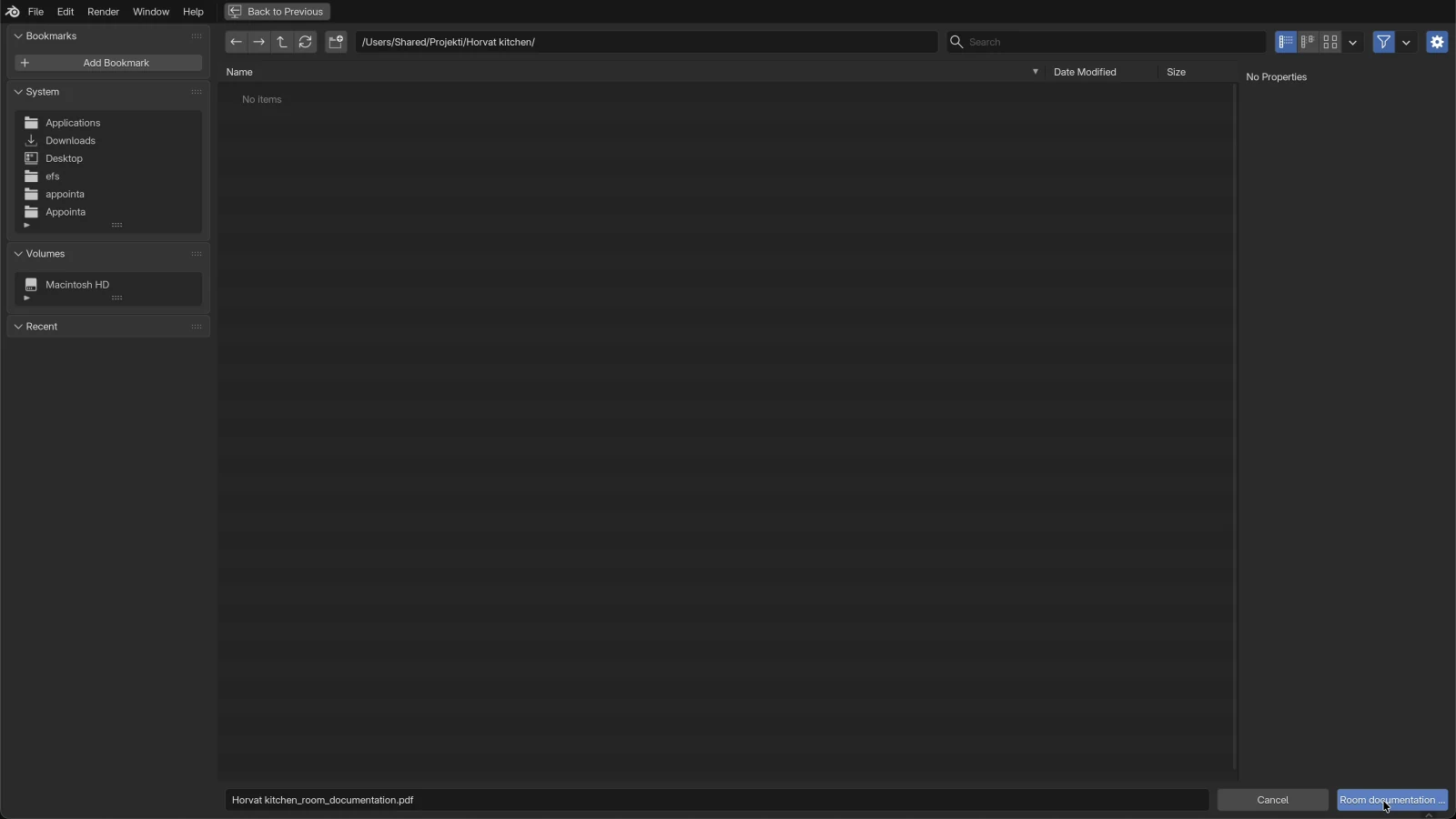
- In the save window EFS suggests the name
Kuhinja Horvat_room_documentation.pdfin the project folder. Click the blue Room documentation (PDF) button at the bottom right. - Open the PDF. The first page is the floor plan, then the elevations of walls A, B, C and D, and the last one is the installation plan.
- In the installation plan, in the Installations the elements need table, the water and drain for the sink and the 400 V connection for the hob are green. Two rows are red: the socket for the cooker hood is 582 mm left of this, and the socket for the fridge is not drawn.
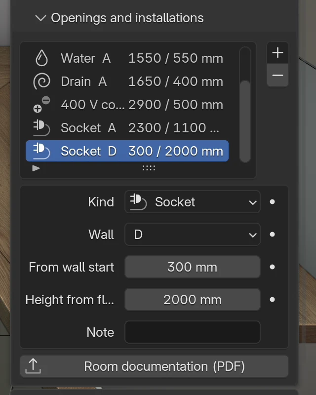
- Add a socket for the fridge: in the Openings and installations box click +, choose Socket, set Wall D, From wall start 300 mm and Height from floor 2000 mm.
- Export again. The fridge row is now green.
Export
The Room documentation (PDF) button is at the bottom of the Openings and installations box, in the Room properties panel. It is shown only while Show room is ticked.
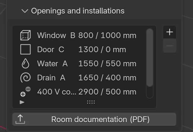
- Click Room documentation (PDF).
- A save window opens with a suggested name and folder.
- Change the folder or name if you need to.
- Click the blue Room documentation (PDF) button or press Enter. Cancel gives up.
- At the bottom of the window EFS reports Room documentation exported: 6 pages. The number of pages depends on the project.
Export settings
The export has no options of its own. You choose only the folder and the file name. Everything else comes from the project.
| What | Where it comes from | Default |
|---|---|---|
| Folder | The folder the project is saved in. | project folder |
| File name | The project name, then _room_documentation.pdf. The project name is the Name field in the Web publish panel; until you type it in, the name of the .blend file is used, and for an unsaved project Project. |
<project name>_room_documentation.pdf |
| Name in the page header | The same project name, at the top right of every page. For an unsaved project without a name it stays empty. | project name |
| Language | The UI language. With the English UI the pages are in English and the file is called …_room_documentation.pdf; with the Croatian UI they are in Croatian and the file is called …_dokumentacija_prostora.pdf. |
UI language |
| Content | Room, openings and installations, cabinets, worktops with cut-outs. | – |
Rules:
- If a file with the same name already exists in the folder, the export replaces it.
- The room documentation is not part of the Production package. Export it with this button (see The production package and the supplier order).
- The PDF is A4, landscape. All dimensions are in millimetres.
What is on which page
| Page | Title | What it shows | When it is there |
|---|---|---|---|
| 1 | Floor plan | The room from above: cabinets, windows, doors, installations, dimensions along the walls. | always |
| 2–5 | Wall A · elevation … Wall D · elevation | Each wall seen from the room: cabinets, worktop, openings, installations, dimensions. | for every wall with a cabinet, worktop, opening or installation |
| last | Installation plan | Mounting heights, the table of openings, the drawn installations and the installations the cabinets need. If it is long, it continues on the next page. | always |
Every page has the title at the top left and the project name at the top right. "Kuhinja Horvat" has six pages: the floor plan, four elevations and the installation plan.
Tip
Send the installation plan to the electrician and the plumber before they come on site, while the installations can still be moved. Give the fitter the whole PDF: the floor plan and elevations show where each cabinet goes and at what height.
Cabinet labels
On the floor plan and the elevations the cabinets are labelled E1, E2, E3… On a wall elevation the label is followed by the cabinet name, e.g. E2 Sink base 800. That way you can find from the floor plan which cabinet is meant.
- A cabinet gets its label at the first export and keeps it in the saved project. A new cabinet gets the next free number.
- The numbers do not run in order along the wall.
- An elevation shows at most 18 characters of the name.
- Cabinets linked in the Relations box (left, right, above, below) are drawn as one cabinet: one rectangle over all of them, with the label and name of the cabinet in whose field they are entered. So the tall fridge unit, built from three carcasses, is one cabinet E9 Fridge. See Relations.
Installation symbols
| Symbol | Installation |
|---|---|
| S | Socket |
| 400 | 400 V connection |
| W | Water |
| D | Drain |
| G | Gas |
The symbols are red: on the floor plan next to the wall, and on an elevation above the red dot that marks the centre of the installation.
Floor plan
The room seen from above, with Wall A at the top of the page, Wall B on the right, Wall C at the bottom and Wall D on the left.
| What | How it is drawn |
|---|---|
| Room | A Width × Depth rectangle, in a thick line. |
| Base and tall units | Filled light blue rectangles with the label (E1…) in the middle. |
| Wall units | A grey dashed outline with the label, over the base units. |
| Window | A thick blue line on the wall, as wide as the window. |
| Door | A thick brown line on the wall, as wide as the door. |
| Installations | A red symbol (S, 400, W, D, G) next to the wall, where the installation is. |
| Dimensions along a wall | A dimension chain outside the room: the ends of the base and tall units along that wall, from corner to corner. Only along a wall with base or tall units; wall units are not in the chain. |
| Overall dimensions | The room's Width above wall A, Depth to the right of wall B. |
In the video the chain along wall A reads 1182, 800, 600, 600 and 50 mm: the corner cabinet, the sink, the dishwasher space, the drawer unit and the gap to wall B.
Wall elevation
Each wall seen from the room, facing the wall. The start of the wall is on the left, as in the Openings and installations box.
| What | How it is drawn |
|---|---|
| Wall | A rectangle as long as the wall and as high as the room's Height. |
| Base and tall units | Light blue rectangles from the bottom to the top of the carcass, with label and name. Legs are not drawn, so there is an empty strip down to the floor under the cabinet. |
| Wall units | Light grey rectangles with label and name. |
| Worktop | A beige strip, from the bottom to the top edge of the worktop. |
| Window, door | A light blue rectangle with the caption Window or Door. The window has a sill height dimension from the floor. |
| Installations | A red dot and the symbol. Each has two dimensions: horizontal from the start of the wall and vertical from the floor. |
| Lower dimension chain | The ends of the base and tall units, from the start to the end of the wall. Below it, the total length of the wall. |
| Upper dimension chain | The ends of the wall units and openings. |
| Height chain on the right | From floor to ceiling, through all the key heights: bottom of the base unit carcasses, top of the carcass, top edge of the worktop, bottom and top edge of the wall units, top of the tall units. |
Example from the video, wall A: the height chain on the right is 100, 720, 38, 572, 720 and 450 mm. These are the legs, the base unit carcass, the worktop, the gap to the wall units, the wall units and the gap to the ceiling, 2600 mm in total.
Note
A corner cabinet belongs to one wall only, the one given by its Z rotation. On the other wall's elevation its place stays empty, and in the lower dimension chain it shows as a gap. In the video the corner cabinet is on the elevation of wall A, and on the elevation of wall D the chain ends with a 1200 mm gap.
Installation plan
The last page. At the top it says: Positions from the start of the wall (facing the wall from the room, the start is on the left), heights from the floor, in mm.
Mounting heights
For every wall with cabinets, heights from the floor in mm. A row is printed only if that wall has what it describes.
| Row | What it is | Kuhinja Horvat, wall A |
|---|---|---|
| Base units, top of the carcass | The top edge of the highest base unit carcass, measured from the floor (the legs are under the carcass). | 820 |
| Worktop, top | The top edge of the worktop along that wall. | 858 |
| Wall units, bottom | The bottom edge of the lowest wall unit. | 1430 |
| Wall units, top (hanging rail about 20 mm lower) | The top edge of the highest wall unit. The hanging rail for the hangers is about 20 mm lower. | 2150 |
| Tall units, top | The top of the highest tall unit. | – (on wall D: 2150) |
If there is no cabinet in the room, instead of the heights it says No elements in the room yet.
Openings
A table of the windows and doors from the Openings and installations box, by wall, and along each wall in order from its start.
| Column | What it is |
|---|---|
| Opening | Window or Door |
| Wall | A, B, C or D |
| From wall start | To the left edge of the opening |
| Width, Height | Size of the opening |
| Sill / from floor | Height from floor: the window sill, 0 for a door |
| Note | Text from the Note field |
The table is not printed if there are no openings.
Installations drawn in the room
All installations from the Openings and installations box: Installation, Wall, From wall start, Height, For and Note.
The For column says which appliance the installation serves, when it is where that appliance needs it (see When an installation is in place). Otherwise it shows —. In the video the water and drain serve the sink, the 400 V connection the hob, and the socket above the worktop nothing.
If no installation is drawn, instead of the table it says None drawn yet…
Installations the elements need
The installations EFS suggests from the cabinets and the worktop cut-outs: Installation, For, Wall, From wall start, Height and In the room.
| In the room | Row colour | What it means |
|---|---|---|
| drawn | green | An installation of that kind is drawn on that wall, where the appliance needs it. |
| N mm left of this | red | There is an installation of that kind on that wall, but not in place. The nearest one is N mm towards the start of the wall. |
| N mm right of this | red | The same, N mm towards the end of the wall. |
| not drawn | red | There is no installation of that kind on that wall. |
Below the table it says: The positions follow the elements and the worktop cut-outs; check them against the appliance makers' installation sheets.
If there is no sink, hob, oven, fridge or dishwasher among the cabinets, instead of the table it says No sink, hob, oven, fridge or dishwasher among the elements…
The result from the video, before the fridge socket was added:
| Installation | For | Wall | From wall start | Height | In the room |
|---|---|---|---|---|---|
| Water | Sink | A | 1582 | 500 | drawn |
| Drain | Sink | A | 1582 | 450 | drawn |
| 400 V connection | Hob | A | 2882 | 500 | drawn |
| Socket | Cooker hood | A | 2882 | 2150 | 582 mm left of this |
| Socket | Fridge | D | 300 | 2000 | not drawn |
The socket for the cooker hood is red because the only socket drawn on wall A is the one above the worktop (2300 mm from the start). EFS takes it as the nearest one and reports that it is 582 mm left of the hob axis.
How EFS knows which installations are needed
Appliances
EFS looks for appliances in two places:
- Worktop cut-outs. A sink cut-out gives the sink axis, a hob cut-out the hob axis. The axis is the middle of the cut-out. See The worktop: cut-outs and the corner joint.
- Cabinet names. If a cabinet name contains one of the words in the table, the cabinet is that appliance, and its axis is the middle of the cabinet. Upper and lower case do not matter. EFS also recognises the appliance names and the names of the built-in templates in every interface language, e.g. the German Geschirrspüler (dishwasher).
| Appliance (For column) | Recognised by | Installations and Height from the floor |
|---|---|---|
| Sink | a sink cut-out; a name with "sudoper" or "sink" (e.g. Sink base 800) | Water 500 mm, Drain 450 mm |
| Hob | a hob cut-out; a name with "kuhanje", "hob" or "cooktop" | 400 V connection 500 mm |
| Cooker hood | comes with every hob, on the same axis | Socket 2150 mm |
| Oven | a name with "pećnic", "pecnic" or "oven" (Oven, Oven high…) | Socket 300 mm |
| Fridge | a name with "hladnjak", "frižider", "frizider" or "fridge" | Socket 2000 mm |
| Dishwasher | a name with "perilica" or "dishwasher" | Socket 300 mm, Water 400 mm, Drain 400 mm |
Rules:
- The appliance is on the wall of its cabinet or worktop. A worktop belongs to the wall it is nearest to.
- If there is a sink cut-out on a wall, a cabinet with "sink" in its name on the same wall does not add a second sink. The same applies to the hob.
- When a name contains the words of two appliances, the longest matching word wins. A cabinet called "Sink and dishwasher" is a dishwasher.
- Every "perilica" (Croatian for washer) means a dishwasher, even in the name "Perilica rublja" (washing machine).
- The heights in the table are EFS defaults, not taken from appliance catalogues. Check them against the manufacturer's instructions.
- No appliance asks for gas. Drawn gas is on the floor plan, the elevation and the table of drawn installations, but not in the comparison.
Tip
The dishwasher space usually has no cabinet, so no installations are suggested for it either. Draw them yourself: Socket, Water and Drain on the wall behind the dishwasher. They will be in the table of drawn installations, with — in the For column.
When an installation is in place
A suggested installation is drawn when there is a drawn installation of the same kind on the same wall:
- at most 150 mm to the left or right of the suggested position, and
- at most 300 mm above or below the suggested height.
If there is no such installation, but there is one of the same kind on the wall, EFS takes the one nearest along the wall and prints how far left or right it is. It does not print the height then.
Watch out
A red row with a small offset, e.g. 20 mm right of this, means the position along the wall is right, but the height is not. Compare Height in the table with the Height from floor of the drawn installation.
Where the program takes heights and positions from
Nothing is typed in by hand. EFS measures the model at the moment of export:
- Position along the wall is the distance from the start of the wall, seen from the room. For cabinets EFS measures all their visible boards; for openings and installations it takes From wall start.
- Heights are from the floor. For cabinets EFS measures the carcass: the legs are not counted, but they raise the carcass. A cabinet on 100 mm legs, 720 mm high, has its carcass from 100 to 820 mm.
- A wall unit is a cabinet with Is upper ticked. Its height comes from the Upper elements height field in the Scene properties panel (default 1430 mm). See Wall units, tall units and flaps.
- A tall unit is a cabinet whose carcass is 1500 mm high or more. The others are base units.
- The cabinet's wall is the wall given by Z rotation: 0° A, 90° B, 180° C, 270° D.
- The worktop is drawn if it was made with the Worktop over selected button. On the elevation it runs from the bottom to the top edge of the worktop, and its top edge goes into Mounting heights.
- The wall's Height on the elevation is the room's Height.
Openings and installations in the PDF
| In the Openings and installations box | Floor plan | Wall elevation | Installation plan |
|---|---|---|---|
| Window | blue line on the wall | Window rectangle, sill height dimension, width in the upper dimension chain | Openings table |
| Door | brown line on the wall | Door rectangle, width in the upper dimension chain | Openings table |
| Socket, 400 V connection, Water, Drain, Gas | red symbol next to the wall | red dot with the symbol, dimensions from the start of the wall and from the floor | Installations drawn in the room table and the comparison in Installations the elements need |
| Note | – | – | Note column |
What the PDF does not show
- Corners, pillars and the sloped roof. On the floor plan and elevations the room is a rectangle. If the fitter needs to know about them, write them in Note.
- Kickboard, fillers, end panels and cornice. Cabinets and worktops are drawn. A narrow gap to the wall, where a filler goes, shows in the dimension chain.
- Fronts hidden with Shift+F. The cabinets are then shallower on the floor plan by the front thickness. Bring the fronts back before export.
- Electrical circuits and pipe diameters. The plan gives positions and heights. Write the rest in Note.
Common problems and solutions
I can't see the Room documentation (PDF) button. The room is not switched on, or the Openings and installations box is closed. In the Room properties panel tick Show room and open the box.
Clicking the button reports that exports are disabled. The trial or subscription has ended. See When the free trial or the subscription ends.
The message Show the room first… The room was deleted, but the checkbox stayed ticked. Untick and tick Show room again, then type in the room's measurements again.
A cabinet is on the wrong wall's elevation. The cabinet has the wrong Z rotation. A cabinet along wall D must have 270°, along wall B 90°. Rotate it with R or the Z rotation button and move it back into place.
The corner cabinet is on only one elevation. That is by design: the corner cabinet belongs to the wall given by its Z rotation. On the other wall a gap is left in the dimension chain.
The sink or hob has no installations in the plan. The worktop has no cut-out, and the cabinet name does not contain a word from the Appliances table. Add a cut-out to the worktop or rename the cabinet, e.g. to "Sink 80".
The socket for the cooker hood is red, but there is a socket on the wall. That is the socket above the worktop. Add a separate socket for the cooker hood on the hob axis, about 2150 mm from the floor.
A row is red, but it shows only a few millimetres. The position along the wall is right; the height differs by more than 300 mm. Correct the installation's Height from floor.
The dishwasher has no installations in the plan. There is no cabinet with "dishwasher" in its name in its place. Draw the socket, water and drain yourself.
Two cabinets are one wide rectangle with one label on the elevation. They are linked in the Relations box. If they should be separate, clear the Left, Right, Above or Below field that holds the neighbour.
A wall has no elevation of its own. That wall has no cabinet, worktop, opening or installation.
The file is called Project_room_documentation.pdf, and the header has no name. The project is not saved and has no name. Save the project (Ctrl+S) or type a Name in the Web publish panel.
The cabinets are shallower on the floor plan than in the 3D view. The fronts are hidden with Shift+F. Bring them back with the fronts icon in the header and export again.
Shortcuts in this chapter
| Key | Action |
|---|---|
| Enter | Confirm the export in the save window |
| Shift+F | Hide the fronts (bring them back before export) |
| R | Rotate the cabinet by 90° so it gets the right wall |
| Ctrl+S | Save the project |
All shortcuts are in the chapter Keyboard shortcuts.
Next
Next chapter: A quote for the customer